OBSIDINENGINEERINGEngineering experience, made executable

We turn drawings
into structured data.
Then we build from it.

Obsidian reads the geometry, tags and relationships in an engineering drawing and writes them into a structured, source-linked record. That record can reconstruct editable CAD, generate registers, cross-check documents and drive repeatable workflows. Any uncertainty is routed to review.

One real drawing  ·  8 source layers121 objects located  ·  every output keeps its source address
Scroll to take the sheet apart

01  ·  The Obsidian advantage

4,000+ projects of experience. Now built into the way we work.

Obsidian has completed more than 4,000 projects across industrial applications. That history gives us more than a portfolio: it gives us a deep body of drawings, standards, workflows and hard-won engineering knowledge.

Project engineering experienceDrawings  ·  methods  ·  standards  ·  workflows
Drawing intelligenceDocument generationReconciliation
Real project experience becomes reusable capability

Proven in the work

Our technology starts with patterns and bottlenecks our teams have encountered on real projects. It does not begin with a generic model of how engineering should work.

Built from practice

Data with context

Drawings, project records and engineering conventions become more valuable when their structure and source context can travel downstream.

Evidence retained

Products, not experiments

We turn repeatable engineering knowledge into systems for drawing recovery, document generation, reconciliation and review.

Made for project delivery

Better for every client

Faster handoffs, more consistent deliverables and clearer traceability. Engineering judgment stays with engineers.

Technology in service of delivery

Obsidian AI turns extensive project engineering experience into systems and products that improve how we deliver, strengthen consistency and create more value for clients.

02  ·  The problem worth naming

The structure is there while it is drawn. It is not there in what gets issued.

Source structure Eight layers.
One drawing space.

Geometry, equipment, fittings, valves, signals, instruments and text remain registered to the same coordinates.

Real source geometry  ·  layers shown at depth  ·  nothing generated

The plot does not carry it.

A P&ID holds tags, sizes, specs and service descriptions as structure while it is being drawn. What leaves the office is usually a plot, so every downstream document starts with a person reading the picture again.

The file had it  ·  the issue does not

When the source files are gone, we can rebuild them.

Drawing sets outlive software, migrations and sometimes the firms that drew them. The plot may be the only record left.

We can rebuild an editable source from that plot, together with the structured record downstream work needs.

Recovered  ·  and worth more than the sheet

Getting the structure back is the point. A register, schedule or cross-check becomes a query against a record, with a route back to the object it came from.

03  ·  First, understand the source

Assess what survived. Choose the right path in.

Before extraction begins, we identify the file format, drawing family, revision metadata, coordinate space and the structure still present. The source decides the pipeline. One model is not asked to solve every drawing the same way.

Native and layered

Layers, blocks, attributes and text survived. We read the file's own organisation and recover geometry, symbols and metadata directly.

DWG  ·  DXF  ·  layered PDF

Flattened vector

The geometry survived, but layers and object meaning did not. We recover strokes, text and repeated symbol patterns, then rebuild their relationships.

Geometry retained  ·  structure rebuilt

Flat and scanned

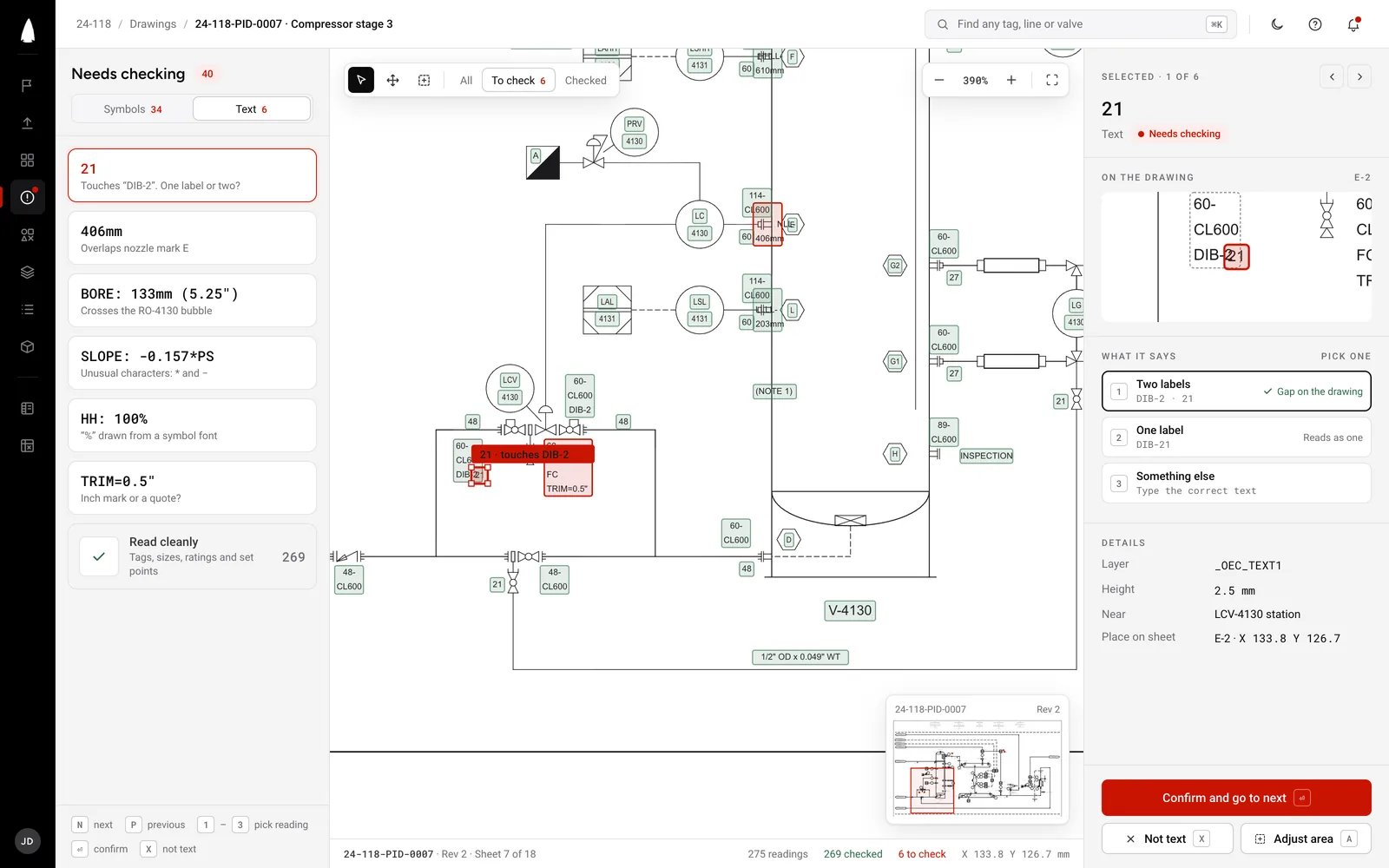
Only pixels remain. Detection, OCR and the client's own drawing conventions rebuild symbols, tags and structure, with uncertainty routed to review.

Image-driven  ·  domain-matched

The assessment establishes what the drawing can tell us directly, what must be reconstructed, and what requires engineering review. It also creates the coordinate frame and provenance needed to trace every later result back to its source.

What the pipeline cannot name, it marks rather than guesses. The review queue is part of the engineering record, not an exception hidden from it.

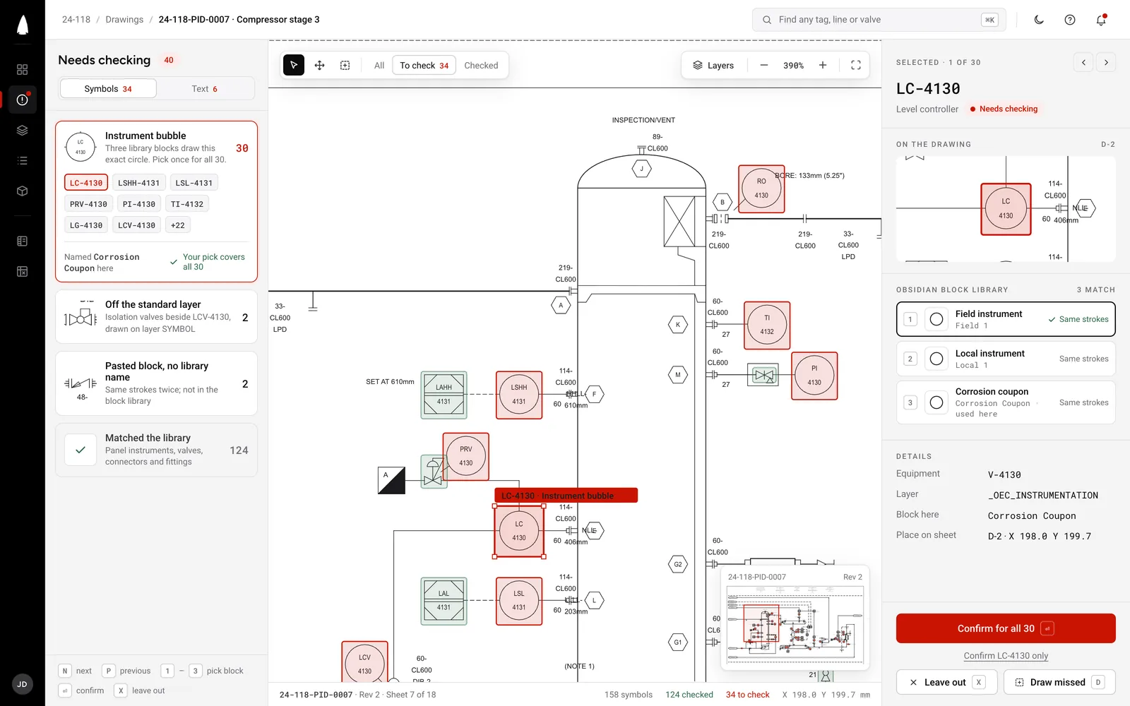
Symbol detection  ·  live capture
One of our own tools, on a real sheet  ·  no audio  ·  19 seconds

04  ·  The worked example

Recover the structure. Give every item an address.

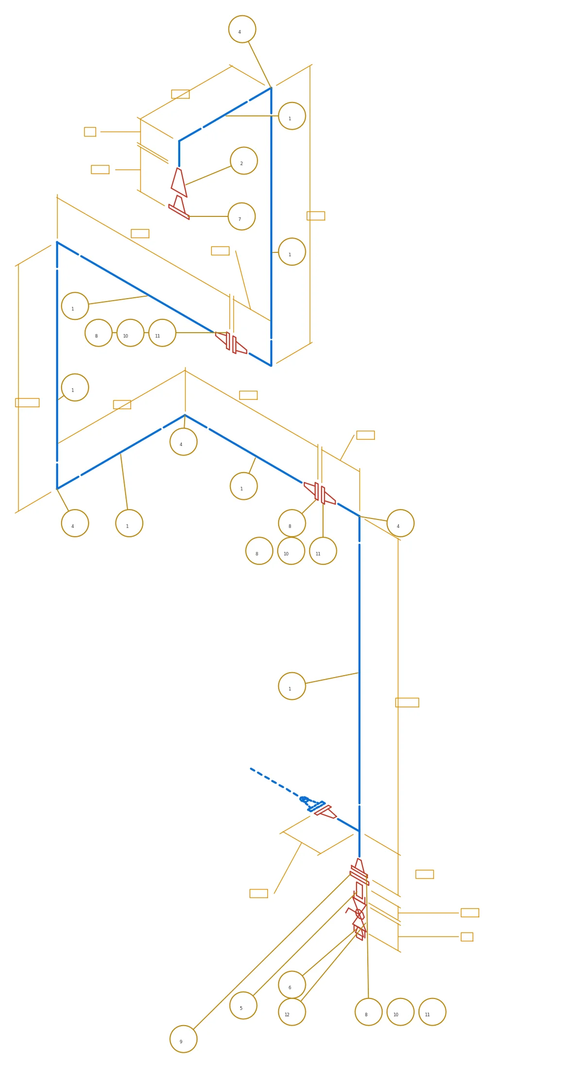
We trace connected linework, locate and classify symbols, read tags, and catalog what each item is, what it looks like, where it resides and what it connects to. Every result keeps its source page, layer, object handle, coordinate and review state.

Process lines
Equipment
Fittings & flanges
Valves
Control signals
Instrumentation
Text & annotation
0Valves
0Instruments
0Fittings
0Flanges
0Layer planes, in register

05  ·  Use case one  ·  Registers

Once the drawing is structured, the registers become queries.

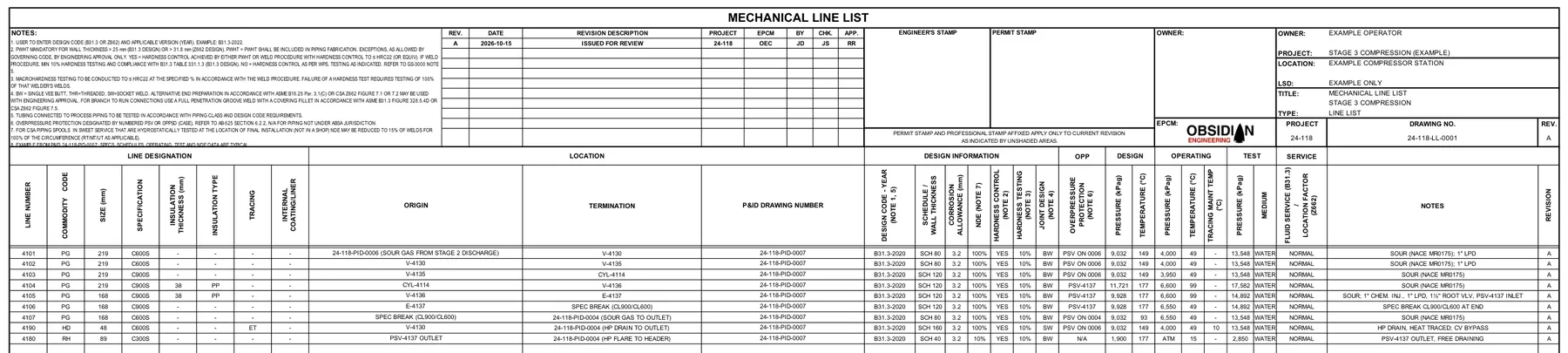
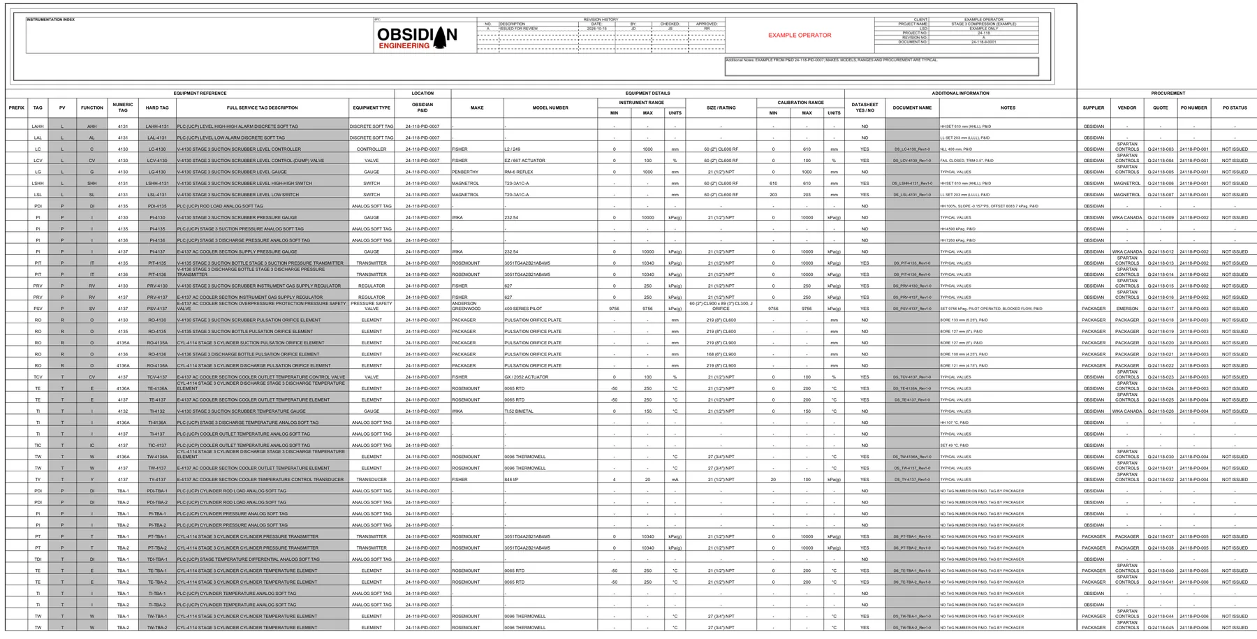
The recovered record produces line, valve, equipment and instrument registers without another manual take-off. Every row keeps its CAD handle and drawing coordinate. Select one below to trace the result back to its source.

0Lines
0Valves
0Equipment items
0Instruments

Once the source structure is recovered, another register is a query rather than another take-off. Device tags are generalised; operator, location and drawing numbers are removed.

06  ·  Use case two  ·  Reconciliation

Connect the records. Surface the disagreements.

The issued documents were checked against the recovered drawing record. Two discrepancies surfaced, each tied to evidence a reviewer can inspect.

Finding 01  ·  tag disagreement

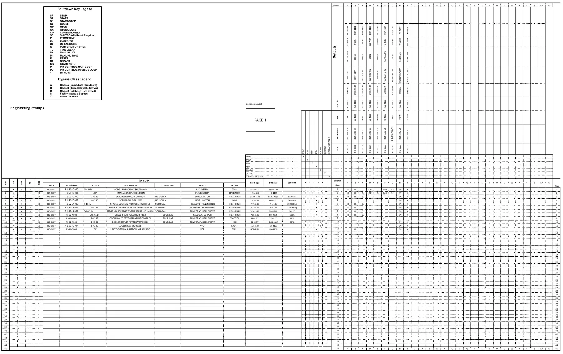
The issued shutdown key names eleven output devices on this sheet. Each one is on the drawing. Two of them are drawn under a different tag family than the key says.

UX-1001
Shutdown key, Rev 14
against
VX-1001
The drawing  ·  instrument layer

There is no UX prefix anywhere on the sheet. Both instances trace to an object handle.

We are not asserting which is right; that is the operator's call. We are surfacing a disagreement that survived fourteen revisions.

Finding 02  ·  the narrative stopped

The vessel's high-high pressure and level trips are both on the drawing. Neither appears anywhere in the issued control narrative, though the equivalent trips on other vessels are documented in it.

The shutdown key kept changing through plant work and annual reviews. The control narrative was not revised once.

Control narrative
Shutdown key
2014201720192022

The two documents drifted apart for eight years, and nothing in either one was capable of noticing.

The value is not automated engineering judgment. It is a reconciled evidence layer that shows an engineer where to look.

07  ·  Use case three  ·  Generation  ·  Live jobs

The P&ID starts the electrical path. Engineering completes it.

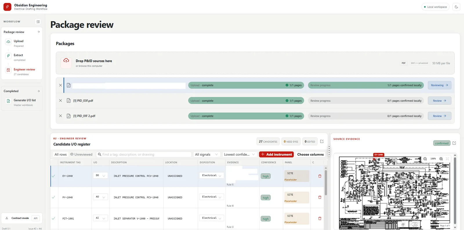
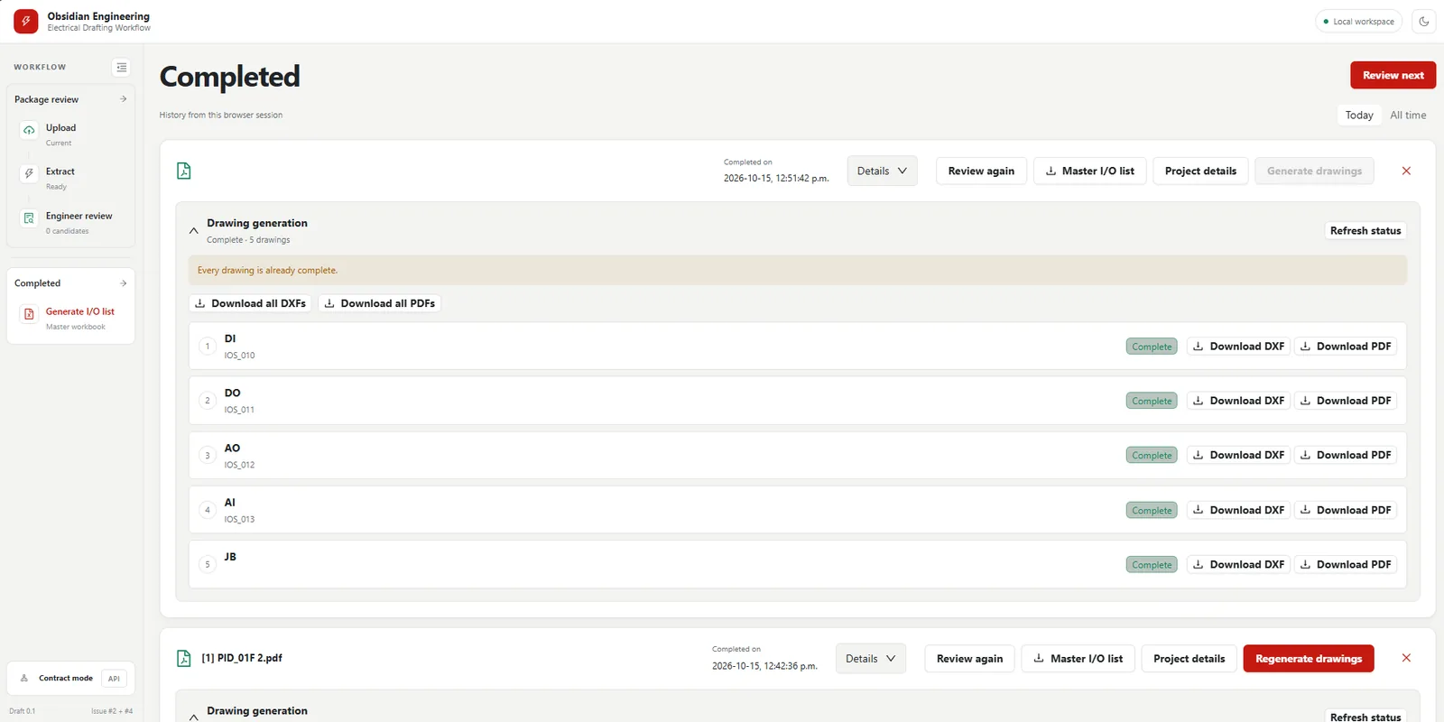
We extract the devices, review the recovered facts, add the design information the P&ID does not contain, and carry the approved record into the electrical deliverables.

01  ·  Source

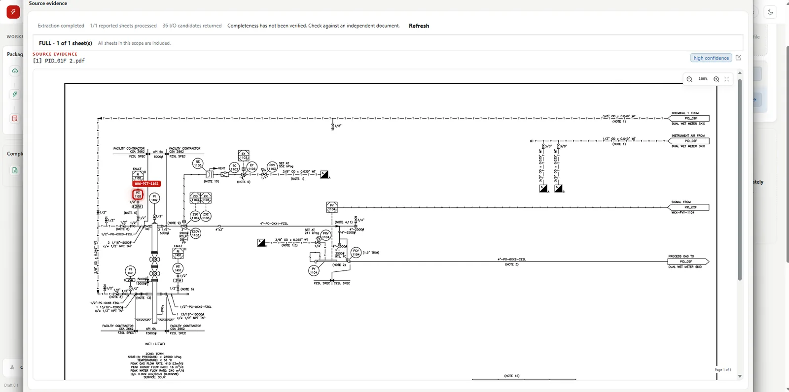
Extract the P&ID devices

Recover tag, function, service and source location from each device symbol.

Recovered facts
02  ·  Review

Validate the device record

Confirm identity, device type, signal and uncertainty against the drawing.

Candidate I/O list
03  ·  Engineering

Complete the I/O design

Add rack, slot, channel, junction box, terminals, cable and wiring decisions.

Engineer governed
04  ·  Delivery

Generate the electrical package

Approved I/O list, I/O schematics, junction-box drawings, and cable and conduit schedules.

In use from approved I/O
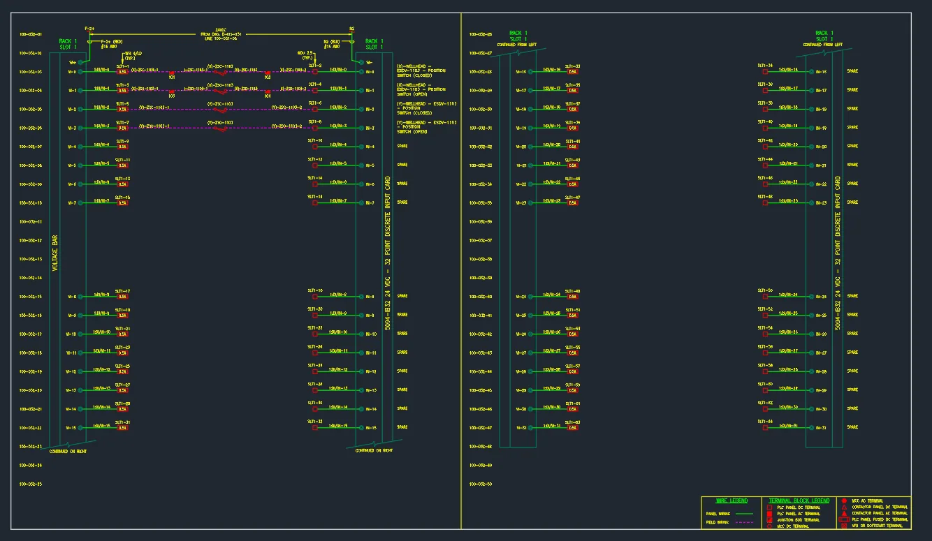
PLC discrete output schematic showing the four shutdown valves
Four P&ID devices  ·  one PLC discrete output schematic
P&ID device  →  PLC output schematic
SAV-1440Drain to condensate stabiliser
SAV-1002Inlet gas to separator valve
SAV-1001To flare blow-down valve
SAV-1000Inlet water to tank ESDV

The seam we are building now: move the reviewed P&ID device record into the electrical workflow without pretending the drawing contains rack, channel or wiring decisions. Function class routes discrete and analog devices to the right drawing family. Engineering completes and approves the record.

Already shipping from approved I/O data: native CAD generated on the client's own drafting profile.

0 client drafting profiles  ·  0 codified redline rules  ·  native CAD out

The boundary matters. Extraction produces the candidate record. Engineers add and approve the design decisions. Approved data drives the deliverables, with termination schedules following the same governed path as a future extension.

08  ·  Rule-driven engineering intelligence

Structure the data. Apply it to the use case.

The application changes, but the core method does not: organise the source structure, preserve the evidence, apply deterministic engineering rules, and produce an output that can be checked.

Isometric clean-up

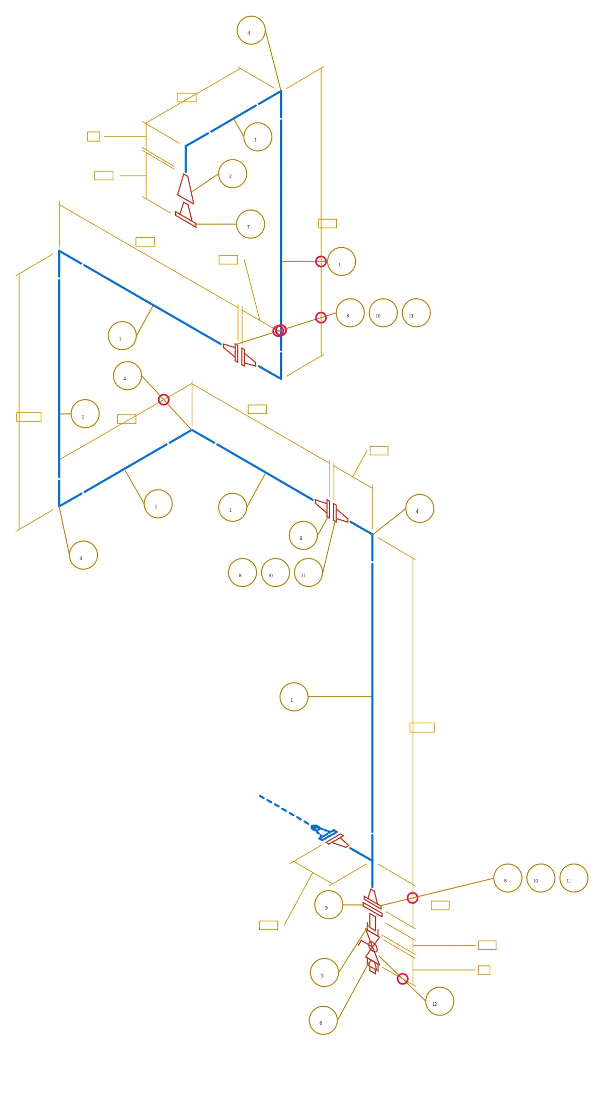
Generated isometrics still need annotation clean-up before issue. We built a solver limited to the moves a drafter already makes: annotation moves, geometry never does.

Sixteen invariant tests assert those constraints on every run.

Isometric before and after annotation clean-up
Before and after  ·  annotation only, geometry untouched

Alignment sheets

An alignment sheet brings survey, GIS, land, crossings and design into one coordinated plan/profile view. The use case structures a family of source data, reconciles what must agree, and applies layout rules to the result.

This capability is in development. The sequence below uses real, generalized project geometry to show the target workflow, not generated output.

Generalized Civil 3D survey basemapSurvey + GIS
Generalized interpreted pipeline corridorCorridor intelligence
Generalized pipeline alignment plan and profile sheetPlan + profile
Real project geometry  ·  client identity removed  ·  target workflow, not generated output

09  ·  One governed record, many products

Structure the drawing once. Build every output from the record.

The path is the product story. Assess the drawing, recover its objects and relationships, validate the structured facility record, then apply that record across engineering delivery.

01  ·  SourceDrawing set

Assess · recover · trace

02  ·  IntelligenceGoverned facility record

Objects · tags · relationships · provenance

Editable CADDemonstrated
Line ListDemonstrated
Valve ListDemonstrated
Equipment ListDemonstrated
Instrument IndexDemonstrated
Electrical PackageIn use
Facility GraphDemonstrated
Document ReconciliationDemonstrated
MTOFuture direction
Shutdown KeyIn development
In useElectrical delivery

Approved I/O list · I/O schematics · Junction-box drawings · Cable schedules · Conduit schedules · Native CAD from approved I/O data

DemonstratedDrawing and facility intelligence

Editable layered CAD reconstruction · Line list · Valve list · Equipment list · Instrument index · Equipment and instrument relationships · Connected drawing graph · Cross-document reconciliation · Revision and document discrepancy reporting · Isometric cleanup

In developmentConnected workflows

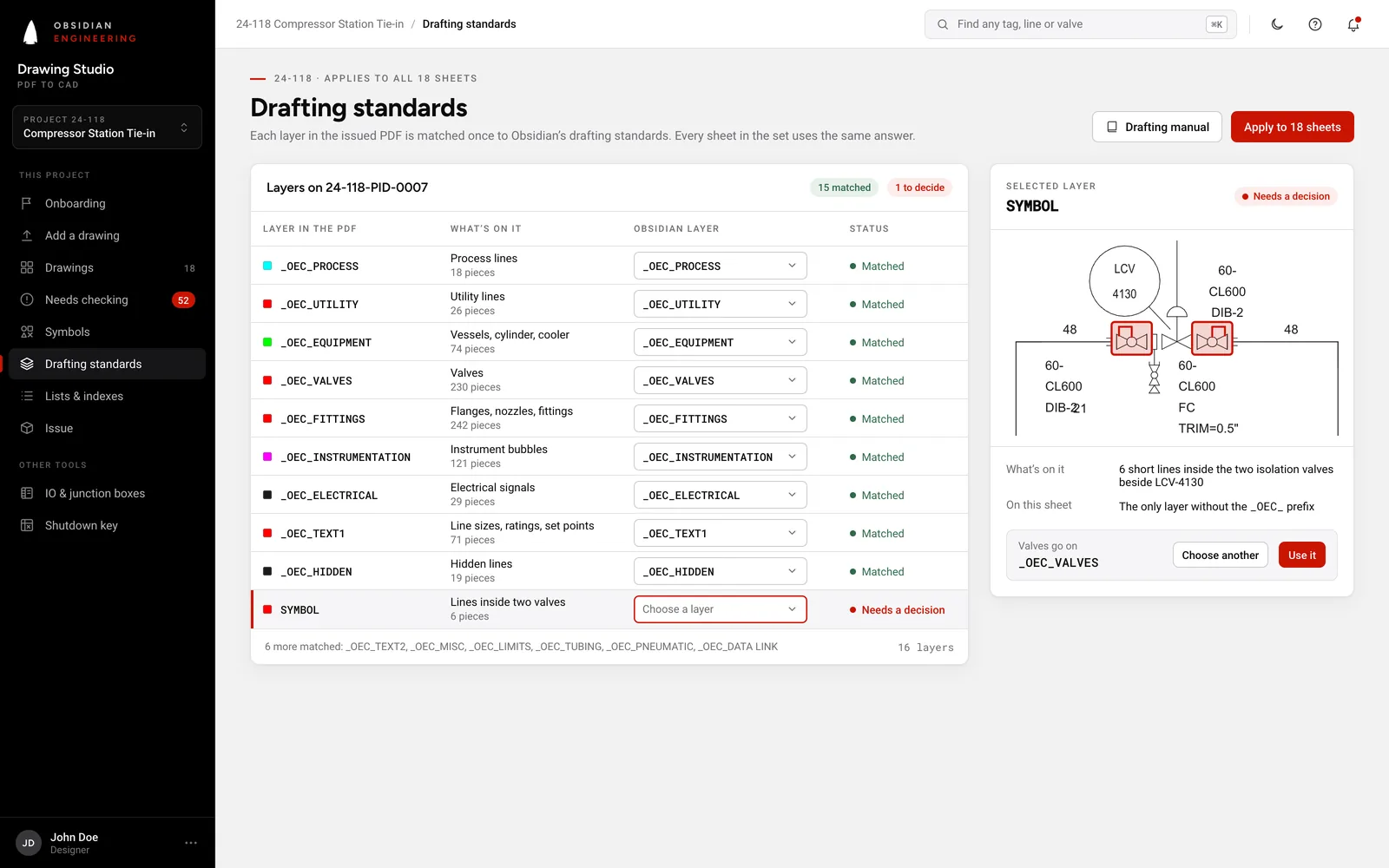
P&ID device handoff · I/O candidate list · Alignment-sheet processing · Shutdown key and cause-and-effect · P&ID versus PLC, DCS or SIS cross-check · Drawing standards and drafting-rule checks

Future directionCoordinated generation

Master tag register · Drawing index and cross-sheet references · Tie-in list · Termination schedules · Missing, duplicate or conflicting tag report · Searchable facility data portal · Symbol-library creation from existing drawing sets · Batch drawing assessment and conversion · Review-ready MTO and procurement packages · DBM, engineering-principle and standards requirements · Control narrative or control philosophy draft · Control narratives and operating documents to enrich the facility record · Drawings, registers and schedules from structured facility inputs · Affected-deliverable regeneration after record changes

The drawing remains the anchor. Project documents and engineering rules add what the drawing does not contain. Engineers retain the design decisions, and every generated result remains reviewable against its source.

10  ·  A practical starting point

One drawing family. One valuable workflow.

Start small enough to verify every result, with a use case valuable enough to matter. The pilot has one source, one structured record and one agreed downstream outcome.

01

Choose the source

One representative drawing family, its source conventions and the related deliverables used today.

02

Build and verify the record

Recover layers, objects, tags and connections. Measure coverage against the source and route uncertainty to review.

03

Apply one use case

Reconstruct editable CAD, generate a register, reconcile documents or apply a defined engineering rule set.

Accuracy is the condition for use. Validation is how the system improves.

Each labelled and validated example adds trusted engineering context for the patterns and exceptions found in real project work. Every result is still measured against its source and routed to engineering review when certainty is insufficient.

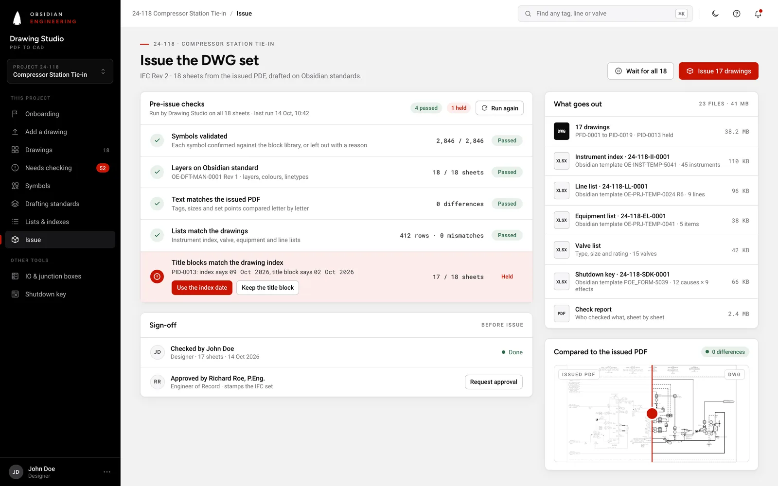
A successful pilot returns a checkable record, a measured workflow result and a clear decision about what to scale next.

Source scopeOne drawing family Target outcomeOne valuable workflow